Lab #7: Using serial communications (SPI controlling an LED driver)
This lab builds on the PWM and RGB LED work we’ve done earlier. The goal is for you to be comfortable with SPI serial communications. This particular device will be one foundation of the Simon game.
What should be turned in?
- Your commented
rainbow_spi.cfile (Canvas)
What should be demo’d live?
- Showing how your RGB led string changes color in an ordered manner.
- The code for this demonstration.
The lab will be due March 1, 2019
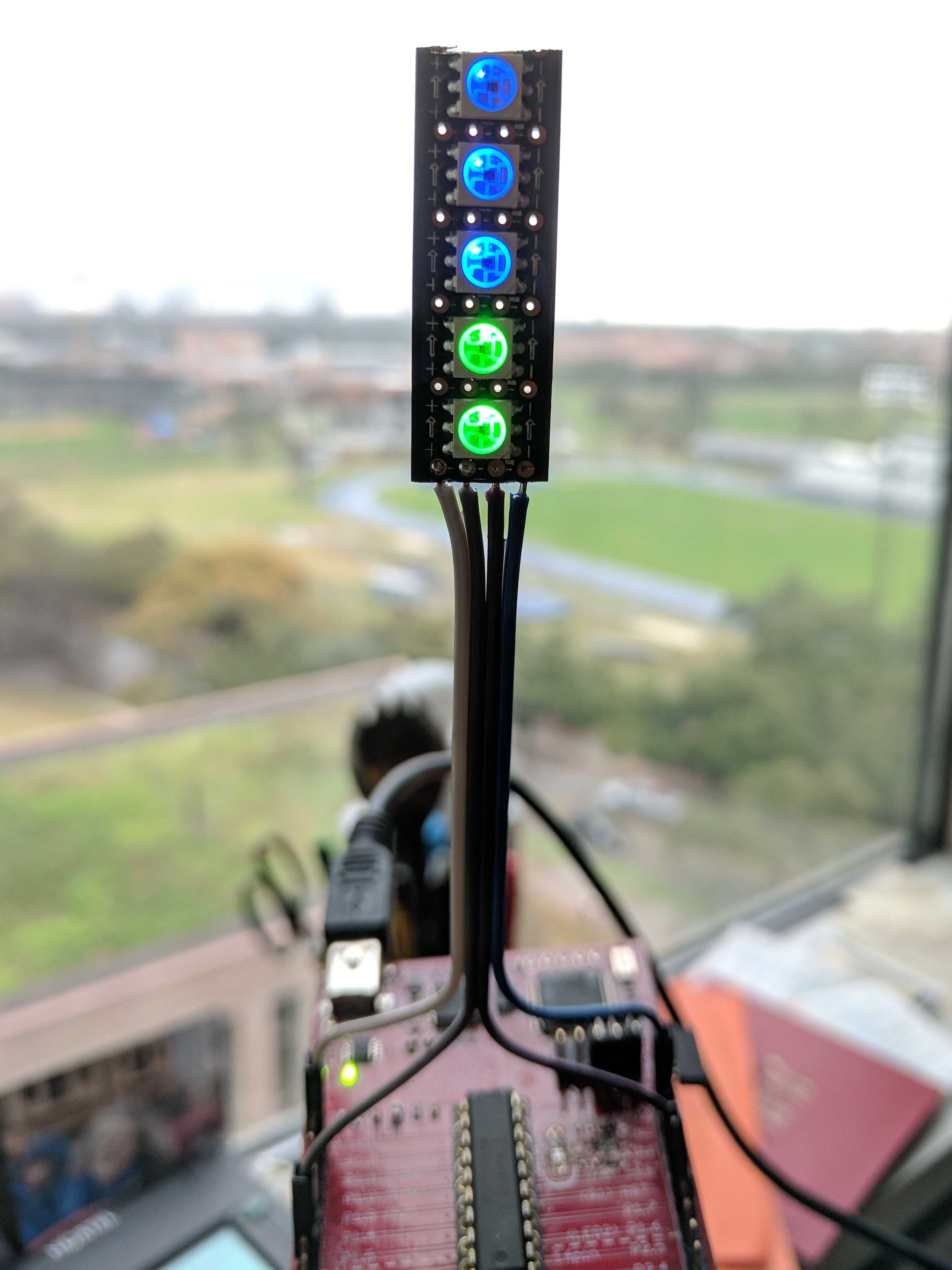
APA102 Strip.

APA102 strip soldering.
Part 0: Solder a APA102C SPI-controlled RGB LED strip to jumper wires
Cut a piece of APA102 strip 5 LEDs long. Take care to leave as much of the perforation intact on the entry side of the strip. (There are directional arrows which point in the direction of signal flow.)
Solder 4 jumper wires to the exposed copper perforation holes as shown in
the second picture to the left. When looking from the front, the 4
perforations are VCC, CLK, DATA, GND. I found that the easiest way to solder
was to first apply lots of flux and then melt solder onto the perforations,
making sure that it actually had flowed onto them. Then, I pre-tinned the
exposed ends of the jumper wires. Finally, I held the jumper wires in place on
each of the perforations and applied heat to reflow the solder. Once you get a
good connection, you may want to apply some epoxy resin over the wires.
SPI control
Let’s review serial communications. Also take a look at the documentation for the APA102 device.
- What are the two categories that all forms of serial communication can be divided into? In which category is the APA102?
- What are two major differences between SPI and I2C serial communications? Which would be best for controlling a large string of LEDs?
- The APA102 uses a modified form of SPI to enable control of multiple LEDs without needing a separate "chip select" line for each one. Briefly describe how it does this.
- How big (in bytes) is the SPI message requried to set the color of a single APA102? How big (in bytes) is the SPI message required to set the color of each LED in a chain of 4 devices?
Now lets review the characteristics of the serial control hardware block in your MSP430s, the USCI.
- How many USCI blocks does the g2553 device have? What three protocols can be controlled by the USCI?
- On your launchpad, one of the serial modules is used to make a UART connection with the host computer (via USB). Which pins and which USCI module are used for this?
- Which pins can be used for the SPI clock and master-out-slave-in (MOSI) data?
Connect your APA102C to the MSP430 using the appropriate SPI clock and MOSI lines. Configure the USCI module so that the SPI clock frequency is within the acceptable range for the APA102C, and the data communication clock edges are proper. Practice sending SPI commands until you figure out how to change the colors of the LEDs (and, optionally, intensity).
Write code to shift the LED colors through a rainbow (starting with red and
going to blue as in Lab 6). There should be 256 color “temperature” levels. Each
LED should cycle one step behind the previous one so that the rainbow appears to
move upward. Use the _16ms watchdog timer interrupt for timing, and increment
the temperature by 16 each time step. Save this as rainbow_spi.c.