Lab #2: Timers and Soldering
_The goals of this lab are two-fold. First, we aim for you to gain experience soldering small, surface mount parts both for skill acquisition and in order to give you some background as you begin PCB design in the next lab. Second, the goal is to begin learning about interrupts, specifically by making use of the interrupt associated with one of the Timer modules.
This assignment is due Monday, February 6, 2017._
Part 1: Soldering a pendant
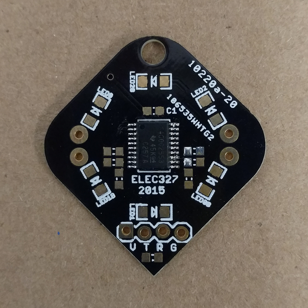
Lab 2 6-LED pendant PCB.
Start by soldering on the MSP430. It is the most challenging piece of the puzzle and getting it in place will make everything else easier. The best bet for dual-inline packages like this one is to tack one corner down, then the opposite one, then fill in the rest.
You may need to reference the board and/or schematic files in order to know what other parts go where. In particular notice which components are resistors, which are capacitors, and which are light emitting diodes (LEDs).
-
Either examine the PCB closely or look at the schematic for the pendant. Which GPIO pins are connected to LEDs?
-
In a normal, canonical (i.e., atomic), forward operating (i.e., not-breaking-down) diode, which terminal does positive (conventional) current flow out of, cathode or anode? In the pendant circuit, which pin is this terminal connected to?
-
What value (0 or 1) will result in the diode turning on? How would the circuit be changed to allow the other value to turn the diode on?
Precise modeling of the current/voltage characteristic of a diode is complicated, but important for a number of applications (such as detecting light with a photo diode). A very simple model of a diode switches from infinite resistance to zero resistance at the “threshold voltage”. Thus, when on, the current through the diode must be limited. A resistor in series with the diode serves to limit the current, and you will see such a resitor in the pendant circuit. In order to find the proper value of this resistance, you need to know something about the LED and also something about the rest of the circuit.
-
Use a multimeter in lab to measure the threshold voltage of the supplied LEDs. How does this compare to the “forward voltage” found in the datasheet.
-
Further examining the datasheet, what is the maximum value of forward current that you should apply? What appears to be the recommended forward current level?
-
Assume that you will be using one a CR2032 battery, which has a nominal voltage of 3V. What voltage will appear on the output of the LED drive pins when they are on? (You can ignore the voltage drop through the MSP430!).
-
Measure the voltage of a new CR2032 - what voltage do you find? After you build the circuit and program the pendant, measure again with the device running. What value do you find now?
-
Finally, assume that the threshold voltage of the diode is 2 V, and the MSP430 output pin voltage is 3 V, and that the desired on current is 5 mA. What value of current-limiting resistor should you use? What would be the minimum resistance such that the current is less than the maximum (DC) specified in the data sheet?
Use the value of resistor which will achieve 5 mA on current along with the LEDs and a 47 K pull-up resitor on the ~RST pin to finish the pendant.
Here is a helpful video:
Part 2: Using the Timer interrupts
The second part of the lab is to program the pendant to do something interesting. The pattern that is desired is as follows:
- One LED should be lit at any one time.
- Which LED is lit should change every 333 ms.
- Which LED is lit should rotate clockwise 3 times, followed by counter clockwise 3 times, then repeating clockwise again, and so on.
Refer to the lab2_skeleton.c file. In order for it to work, you will need to
set up the proper GPIO pins (lines 26-30), and properly set/reset GPIO in the switch statement.
You need to create a next_led() function, which should return the values 0 through
5, indicating the next LED to be lit, and maintaining state from one function call to another.
You will also need to adjust the clocks and timer interrupt setup code to achieve the desired
timing. In principle, the code could all go in the interrupt, but in general it is best to have
interrupt service routines execute as quickly as possible. BONUS: Make
next_led() return an unsigned int, with the higher byte corresponding to PORT2 and
the lower byte to PORT1. Then eliminate the switch statement and directly write the PORT1/2
values after the function call. SUPER BONUS: In addition to the pendant pattern described
above, program the pendant to operate as a clock. Represent the second hand as a flashing LED
that moves around the circle, blinking at 1 Hz in each position 6 times. In addition, light
up the LEDs that correspond to the hour hand and the minute hand, assuming that we have a day
divided into 4 six hour segments rather than two twelve hour ones. Or figure out another cool
way of making a clock.
To answer the following questions, you will need to refer to Chapters 5 and 12 of the User Guide.
-
How do you set a pin to be an output? What is the default mode for GPIO pins?
-
If your main function begins with the instruction
BCSCTL2 = 0;what will be the frequency of the CPU clock (MCLK)? What will be the frequency of the submain clock (SMCLK)? (Hint: you will also need to figure out what the default setting for the DCO is, and assume that it is set.) (Second hint: the DCO in the MSP430g2553 is calibrated by default.) -
Assume that the SMCLK has been configured to 1 MHz. Assume you are given the following configuration of Timer A0:
TA0CTL = TASSEL_2 | ID_3 | MC_1 | TAIE;. What register do you need to set, and to what value in order to generate interrupts every 1 millisecond? -
Instead, assume you are given the following configuration of Timer A0:
TA0CTL = TASSEL_2
| ID_3 | MC_2 | TAIE;
. You can still achieve a 1 ms interrupt, but now you will additionally be required to update the register in the previous question in your ISR. What is the proper update command? (Hint: the right answer does not involve changingTA0CTL.) What would happen to your program if you forgot to initialize the register in your main function and only modified it in the ISR?
Save your code as pendant.c. Create a demo video that shows the pendant operating.
Upload your answered questions, code and the video URL to Canvas.