[NOT FINAL] Lab #8: Motor Speed Control
There are three goals for this assignment:
- To gain experience with motors, Hall-effect sensors, and LCD displays
- To construct software which carries out feedback-control in real-time.
What should be turned in?
- Your commented code files.
- Your answers to the questions. (Please submit in either PDF or TXT format.)
- A youtube link to a demo video showing speed control.
Motor speed control with PWM
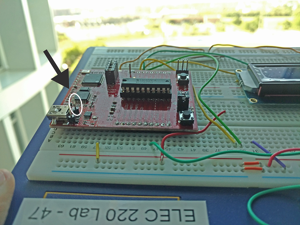
The motors in your Launchpad Sidekick kits require more than 3V to operate. Thus, you will need to hook into a 5V supply in order to drive them. The test point to the right of the USB connector on your g2553 Launchpads provides a 5V source. Use an N-channel mosfet to control the motor, driving the gate with PWM.

Task 1: Wire up your motor to your launchpad:
- Connect the two inputs of the motor to your breadboard. Tape/glue a circle of cardboard to the drive pin of the motor so that you can see the motor rotating.
- The N-channel MOSFET transistor will act as a switch on the “low-end” of the motor. Thus, you should connect the Drain of the transistor to one wire of the motor, and +5V to the other wire. The Source of the transistor should be connected to ground, and the Gate should be connected to a PWM drive pin of the MSP430.
- Use PWM to drive the motor at different speeds.
Showing information via an LCD display

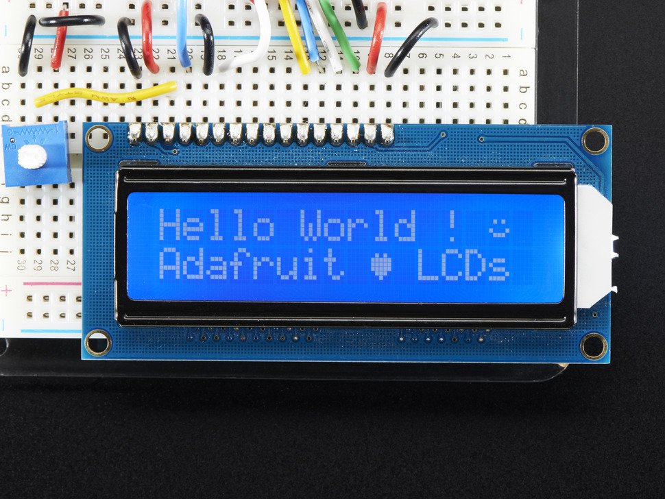
The product page for the LCD display is here. You will also find two data sheets - the primary one and one with more detail about the character maps.
Task 2: Display a message on the LCD display.
- Wire up the LCD display either in 4 pin or 8 pin mode.
- Display the message “000 RPM”.
- Write a function to send out an arbitrary RPM message.
Measuring rotation speed using a Hall-effect sensor

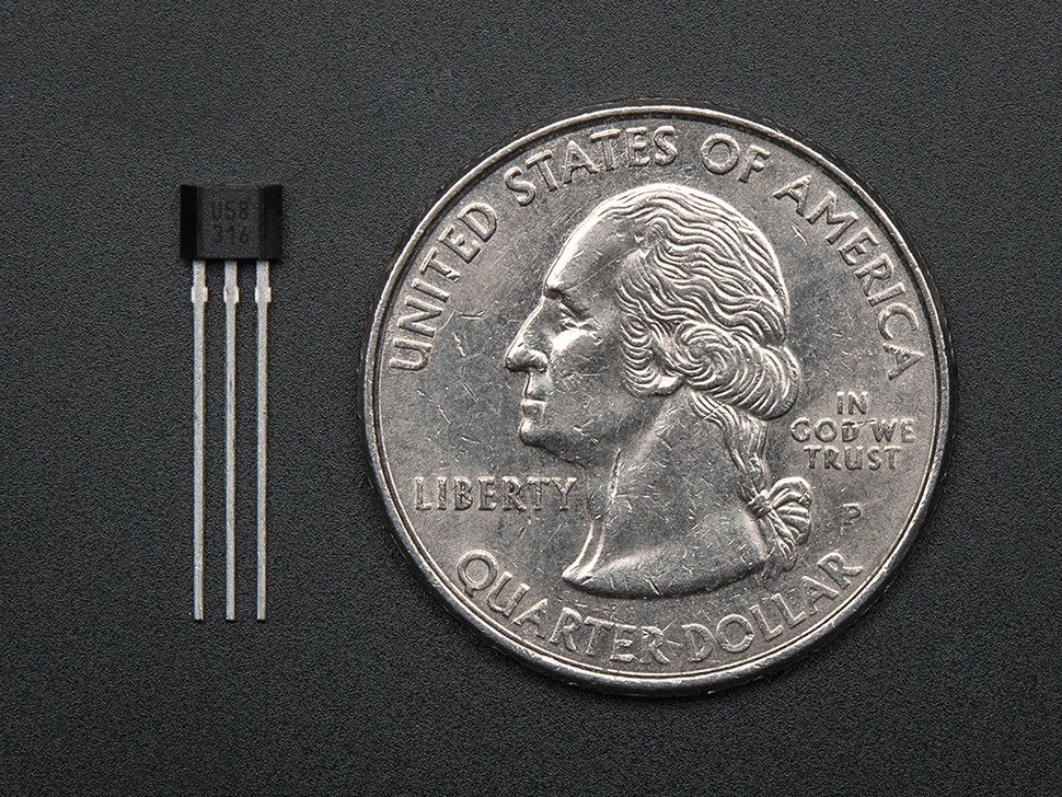
The product page for the hall-effect sensor is here. Datasheet.
Task 3: Integrate the Hall sensor.
- Add the Hall sensor to your breadboard with the input connected to a MSP430 pin.
- Implement a magnetic switch where bringing a magnet close to the sensor turns off/on the LED. (This will help you understand the effect of magnet distance and orientation.)
Final device
Now, put it all together. Add the magnet to the carboard being driven by the motor. Count the sensed magnetic switches and use this to set the PWM level to achieve a particular level of RPMs. Film a video where the motor runs at 10 RPM for 30 s and then 30 RPM for 30 s. Turn in your video and code!