Lab #6: Using serial communications (SPI controlling an LED driver)
This lab builds on Lab 4. The goal is for you to be comfortable with SPI serial communications that will be the foundation of the Simon game.
Part 0: Solder a APA102C SPI-controlled RGB LED to a breakout board
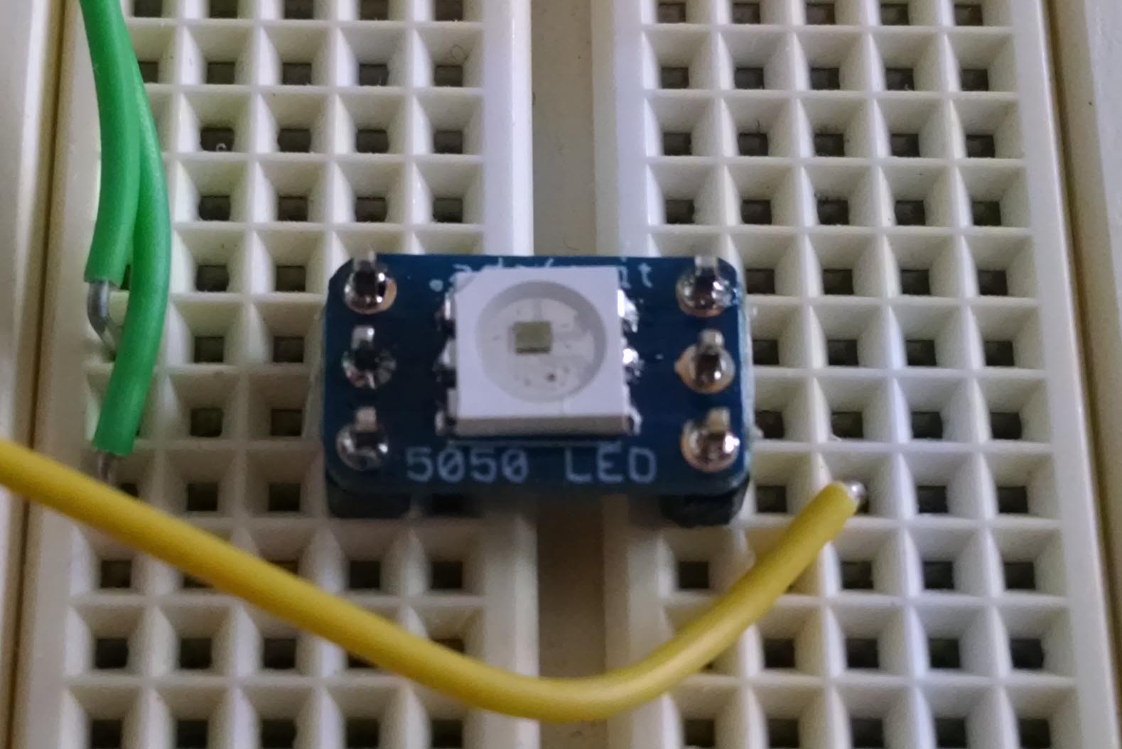
Solder one of the SPI-controlled LEDs to a “5050” breakout board. Additionally, solder pin headers to the 6 pins so that you can plug the breakout board into a solderless breadboard. To make sure the pins are parallel it can help to hold it in the breadboard while soldering. Caution: if you apply too much heat you’ll melt your breadboard!
Part 1: SPI control
Let’s review serial communications. Also take a look at the documentation for the APA102 device.
- What are the two categories that all forms of serial communication can be divided into? In which category is the APA102?
- What are two major differences between SPI and I2C serial communications? Which would be best for controlling a large string of LEDs?
- The APA102 uses a modified form of SPI to enable control of multiple LEDs without needing a separate "chip select" line for each one. Briefly describe how it does this.
- How big (in bytes) is the SPI message requried to set the color of a single APA102? How big (in bytes) is the SPI message required to set the color of each LED in a chain of 4 devices?
Now lets review the characteristics of the serial control hardware block in your MSP430s, the USCI.
- How many USCI blocks does the g2553 device have? What three protocols can be controlled by the USCI?
- On your launchpad, one of the serial modules is used to make a UART connection with the host computer (via USB). Which pins and which USCI module are used for this?
- Which pins can be used for the SPI clock and master-out-slave-in (MOSI) data?
Connect your APA102C to the MSP430 using the appropriate SPI clock and MOSI lines. Configure
the USCI module so that the SPI clock frequency is within the acceptable range for the APA102C,
and the data communication clock edges are proper. Practice sending SPI commands until you
figure out how to change the LED color (and, optionally, intensity). Convert your Lab 4 code to
now drive the APA102C according to the temperature (and randomness). Turn this code in as
spi_led_temperature.c. BONUS: You can continue to do the “heartbeat” functionality to
receive a bonus. However, now you should do this using the “global intensity” bits. Make a
video showing your APA102C being controlled by the temperature of the launch pad as in Lab 4.
Turn in the answers to the questions, your code, and a video URL on Canvas.